
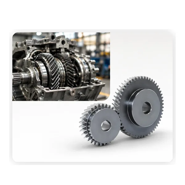
Description
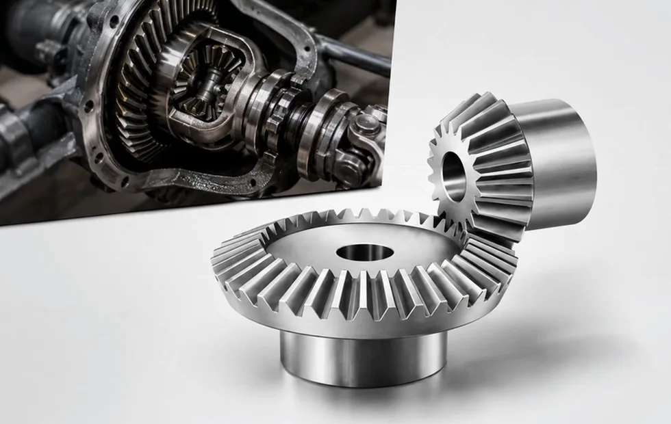
Engineering configuration overview
The selected structured product source identifies Module 2, DIN 6 / Grade 5 precision. The page is designed for procurement and engineering review: source-supported values are shown explicitly, while application-dependent values remain confirmation fields.
Best RFQ starting point: required tooth count and mating gear/rack, module, pressure angle and helix hand, bore, keyway or clamp interface, face width and available envelope.
- Use the latest drawing or measured interface sketch.
- State normal and peak duty separately.
- Mark every unknown value for engineering confirmation.
Product overview
The selected structured product source identifies Module 2, DIN 6 / Grade 5 precision. This information is a selection boundary, not a substitute for the approved order drawing. The quotation should state which source-backed family or configuration is being offered and list any deviations or open engineering items.
The cited helix is left-hand 19°31′42″. This information is a selection boundary, not a substitute for the approved order drawing. The quotation should state which source-backed family or configuration is being offered and list any deviations or open engineering items.
40Cr and 20CrMnTi are source-supported material choices, with HRC45–55 shown for the referenced family. This information is a selection boundary, not a substitute for the approved order drawing. The quotation should state which source-backed family or configuration is being offered and list any deviations or open engineering items.
The source lists bore coverage from Ø14 to Ø50 mm and matching M2 rack 552020. This information is a selection boundary, not a substitute for the approved order drawing. The quotation should state which source-backed family or configuration is being offered and list any deviations or open engineering items.
Module 2 Ground Helical Pinion Gear should be compared on the basis of the complete application. An apparently similar component can differ in interface, load distribution, lubrication, sealing or transient duty. A purchasing description that includes those conditions is more useful than copying a short catalogue name.
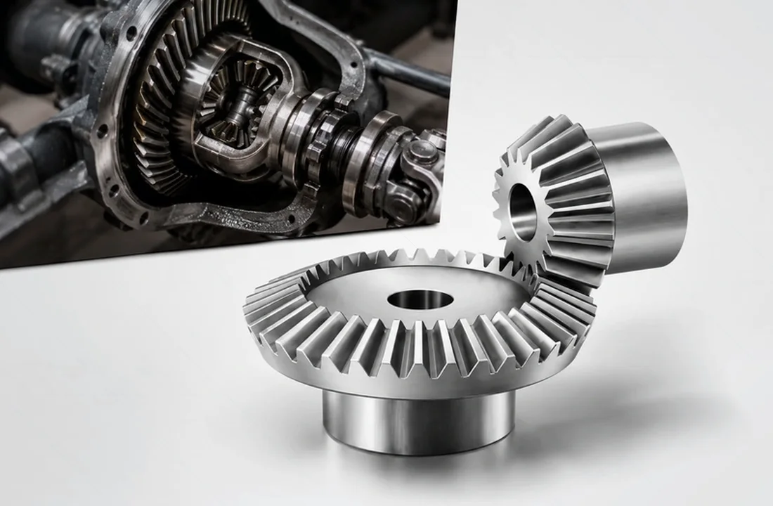
Structure and interfaces
The interface review identifies every surface or connection that can make a replacement fit or fail to fit. For this product, record required tooth count and mating gear/rack, module, pressure angle and helix hand, bore, keyway or clamp interface. Add a marked-up drawing or dimensioned photographs when an original drawing is unavailable. If one dimension is derived rather than measured, label it as an assumption.
Also note the mating component and the direction of load. This is essential because shaft shoulders, keys, splines, bolt circles, pins, port orientation, joint angles or process connections can all be correct individually while still being incompatible as an assembled system.
Technical specification reference
| Module | 2 |
|---|---|
| Quality reference | DIN 6 / Grade 5 |
| Helix | LH 19°31′42″ |
| Materials in source | 40Cr / 20CrMnTi |
| Hardness in source | HRC45–55 |
| Bore family in source | Ø14–Ø50 mm |
| Matching rack reference | 552020 M2 |
This table contains only the selected-source values that are suitable for publication. All other dimensions, loads and performance data are released against the specific enquiry and final drawing.

Applications and duty conditions
Typical application contexts include CNC axis drives, rack-and-pinion positioning, automation machinery, custom gear trains. These examples help identify the environment and load path; they are not claims of a specific customer installation. Selection should account for normal load, peak or shock load, start/stop behavior, contamination, temperature, alignment and the consequences of an unexpected stop.
For a replacement, include the reason the old unit is being changed. Repeated wear, overheating, noise, leakage or fracture can indicate a system condition that should be corrected before installing a new part.
Selection and customization guide
- 1. Confirm required tooth count and mating gear/rack. Record the value, unit, source and tolerance where relevant. If it is unknown, mark it for engineering confirmation instead of estimating it.
- 2. Confirm module, pressure angle and helix hand. Record the value, unit, source and tolerance where relevant. If it is unknown, mark it for engineering confirmation instead of estimating it.
- 3. Confirm bore, keyway or clamp interface. Record the value, unit, source and tolerance where relevant. If it is unknown, mark it for engineering confirmation instead of estimating it.
- 4. Confirm face width and available envelope. Record the value, unit, source and tolerance where relevant. If it is unknown, mark it for engineering confirmation instead of estimating it.
- 5. Confirm material/heat treatment requirement. Record the value, unit, source and tolerance where relevant. If it is unknown, mark it for engineering confirmation instead of estimating it.
- 6. Confirm accuracy, noise, speed and lubrication target. Record the value, unit, source and tolerance where relevant. If it is unknown, mark it for engineering confirmation instead of estimating it.
Customization should be tied to a functional reason: an interface, duty, material, finish, guarding, inspection or service requirement. That keeps the quotation comparable and prevents cosmetic customizations from obscuring the technical basis.
Installation, inspection and maintenance
Before installation, verify the released drawing or configuration against the machine. Clean mating surfaces, check fasteners and alignment, and make sure guards and service access are restored. Rotating parts should be turned or jogged under controlled conditions before full-duty operation where the machine procedure permits it.
Initial inspection should focus on abnormal heat, noise, vibration, leakage, movement, fastener loosening or contact marks. Maintenance intervals should follow the actual environment and operating hours. Dust, moisture, shock and frequent reversals usually justify more frequent visual checks than clean continuous service.
Quality and release checks
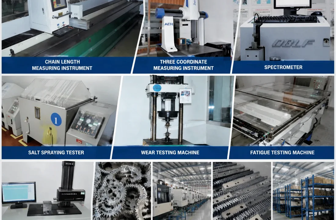
The purchase order should define what is measurable: material where required, critical dimensions and datums, interface features, surface/heat-treatment requirements when source-supported, and any inspection report needed for acceptance. Avoid requesting a certificate or quality label without defining the feature that matters to the application.
For custom parts, inspection records should be traceable to the released drawing revision. For complete equipment, functional checks should be tied to agreed inlet/outlet or operating conditions rather than generic performance language.
- Drawing revision and controlling dimensions
- Material or finish only where required by the order
- Functional acceptance tied to the stated duty
FAQ
Can you quote from an old part number only?
An old number is a useful starting point, but final release still requires enough interface and application data to avoid a wrong revision or undocumented modification.
Can the product be customized?
Where the selected product family supports configuration, the quotation can address drawing, interface, material or option changes after engineering review. Unsupported numeric ranges are not assumed on this page.
What should I send with the RFQ?
Send the latest drawing or measured interfaces, operating speed/load, duty cycle, environment, quantity and any inspection requirement. Complete-equipment enquiries also need process and utility data.
Related engineering guidance
Review the Gears category and the engineering selection workflow before finalizing the enquiry.
- Confirm the product-family selection.
- Cross-check the application duty and mating interfaces.
- Carry the same assumptions into the RFQ and released drawing.
Request a Module 2 Ground Helical Pinion Gear quotation
Use the form below or email the engineering sales team. Include the data listed above so the reply can be tied to a real application rather than a generic assumption.
- Drawing or measurable interfaces
- Operating duty and environment
- Quantity and acceptance requirements
Turn the helical gearing enquiry into an approvable configuration
The final decision should not depend on a catalogue title alone. Build a short release record that links the selected family to the actual machine or process. For this product, the controlling inputs are module, tooth count, helix hand/angle, face width, bore/shaft, material/hardness and mating rack/gear. Record the source of every important value—drawing, direct measurement, operating record or engineering calculation—and keep assumptions visible until they are confirmed.
Separate normal duty from credible peaks. A component can appear correct at steady state and still be unsuitable during startup, reversing, turning, plugging, thermal excursion, pressure spike or other transient. If a protection device, guard, filter, relief function, torque limiter or process interlock is expected to manage that event, state the intended behaviour rather than only increasing a generic safety factor.
Approve what has to fit before production begins
A released drawing or configuration record should identify the datums and mating features that control installation. For a replacement, use the old part number as a reference but verify the dimensions that can detect a wrong or superseded identification. For a new design, link each custom dimension to a machine or process need. This keeps dimensional changes from becoming informal email instructions that are difficult to inspect later.
Confirmed
Values taken from the controlling drawing, approved data sheet or direct measurement with units.
Derived
Calculated or inferred values with the basis recorded so another engineer can reproduce the reasoning.
Open
Unknown or application-dependent items that remain explicit supplier questions rather than guessed specifications.
Check the system around the new part
Before full-duty operation, verify alignment, mounting, fasteners, guards, lubrication/filtration, clearances and the complete range of machine movement. Where the operating procedure permits, start under controlled conditions and look for abnormal temperature, vibration, noise, leakage, contact marks, looseness or unexpected control behaviour. A recurring symptom should trigger a root-cause check of the surrounding machine instead of automatic like-for-like replacement.
Record the as-installed configuration and any commissioning observations. That record becomes useful when maintenance later needs to distinguish normal wear from an interface, contamination or overload problem.
Make receiving inspection proportional to risk
The purchase order should identify the revision and the features that matter to fit and function. Material, finish, heat treatment, performance test or certificate requirements should be requested where they support the application—not as a generic list copied from another job. For custom products, critical dimensions should be traceable to the released drawing. For complete equipment, functional acceptance should be tied to agreed inlet/outlet, duty or process conditions.
- Controlling drawing or configuration revision
- Critical interfaces and units / tolerances
- Normal and peak duty used for selection
- Required material, treatment or protection where applicable
- Inspection / functional evidence required at acceptance
- Remaining confirmation items closed before release
Reviews
There are no reviews yet.